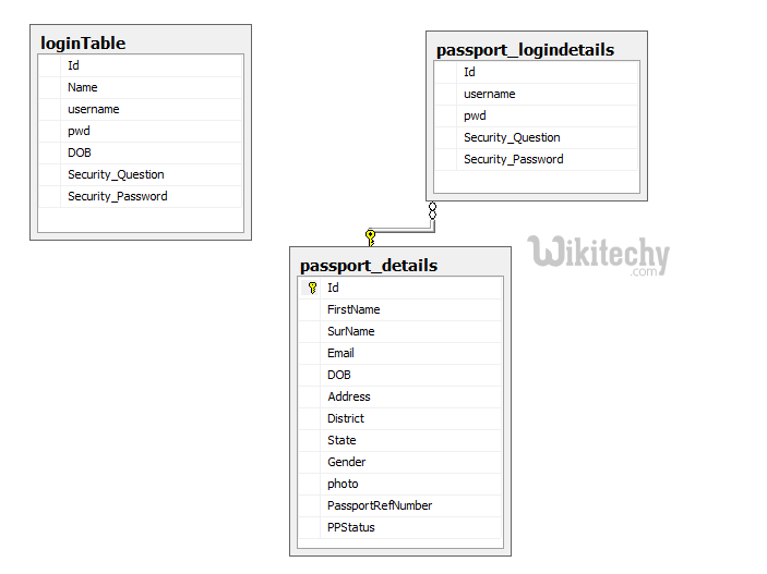
Passport Status Tracking System - ER Diagram
ER diagram
- Entity Relationship Diagram, also known as ERD, ER Diagram or ER model, is a type of structural diagram for use in database design.
- An ERD contains different symbols and connectors that visualize two important information: The major entities within the system scope, and the inter-relationships among these entities.
- And that's why it's called "Entity" "Relationship" diagram (ERD)!
ER diagram
Uses of entity relationship diagrams
- Database design: ER diagrams are used to model and design relational databases, in terms of logic and business rules (in a logical data model) and in terms of the specific technology to be implemented (in a physical data model.) In software engineering, an ER diagram is often an initial step in determining requirements for an information systems project. It’s also later used to model a particular database or databases. A relational database has an equivalent relational table and can potentially be expressed that way as needed.
- Database troubleshooting: ER diagrams are used to analyze existing databases to find and resolve problems in logic or deployment. Drawing the diagram should reveal where it’s going wrong.
- Business information systems: The diagrams are used to design or analyze relational databases used in business processes. Any business process that uses fielded data involving entities, actions and interplay can potentially benefit from a relational database. It can streamline processes, uncover information more easily and improve results.
- Business process re-engineering (BPR): ER diagrams help in analyzing databases used in business process re-engineering and in modeling a new database setup.
- Education: Databases are today’s method of storing relational information for educational purposes and later retrieval, so ER Diagrams can be valuable in planning those data structures.
- Research: Since so much research focuses on structured data, ER diagrams can play a key role in setting up useful databases to analyze the data.
The components and features of an ER diagram
ER Diagrams are composed of entities, relationships and attributes. They also depict cardinality, which defines relationships in terms of numbers. Here’s a glossary:
Entity
- A definable thing-such as a person, object, concept or event-that can have data stored about it. Think of entities as nouns. Examples: a customer, student, car or product. Typically shown as a rectangle.
- Entity type: A group of definable things, such as students or athletes, whereas the entity would be the specific student or athlete. Other examples: customers, cars or products.
- Entity set: Same as an entity type, but defined at a particular point in time, such as students enrolled in a class on the first day. Other examples: Customers who purchased last month, cars currently registered in Florida. A related term is instance, in which the specific person or car would be an instance of the entity set.
- Entity categories: Entities are categorized as strong, weak or associative. A strong entity can be defined solely by its own attributes, while a weak entity cannot. An associative entity associates entities (or elements) within an entity set.
- Entity keys: Refers to an attribute that uniquely defines an entity in an entity set. Entity keys can be super, candidate or primary.
- Super key: A set of attributes (one or more) that together define an entity in an entity set.
- Candidate key: A minimal super key, meaning it has the least possible number of attributes to still be a super key. An entity set may have more than one candidate key.
- Primary key: A candidate key chosen by the database designer to uniquely identify the entity set.
- Foreign key: Identifies the relationship between entities.
Relationship
- How entities act upon each other or are associated with each other.
- Think of relationships as verbs. For example, the named student might register for a course.
- The two entities would be the student and the course, and the relationship depicted is the act of enrolling, connecting the two entities in that way.
- Relationships are typically shown as diamonds or labels directly on the connecting lines.
- Recursive relationship: The same entity participates more than once in the relationship.
Attribute
A property or characteristic of an entity. Often shown as an oval or circle.
- Descriptive attribute: A property or characteristic of a relationship (versus of an entity.)
- Attribute categories: Attributes are categorized as simple, composite, derived, as well as single-value or multi-value.
- Simple: Means the attribute value is atomic and can’t be further divided, such as a phone number.
- Composite: Sub-attributes spring from an attribute.
- Derived: Attributed is calculated or otherwise derived from another attribute, such as age from a birthdate.
- Multi-value: More than one attribute value is denoted, such as multiple phone numbers for a person.
- Single-value: Just one attribute value. The types can be combined, such as: simple single-value attributes or composite multi-value attributes.
Cardinality
- Defines the numerical attributes of the relationship between two entities or entity sets.
- The three main cardinal relationships are one-to-one, one-to-many, and many-many.
- A one-to-one example would be one student associated with one mailing address. A one-to-many example (or many-to-one, depending on the relationship direction): One student registers for multiple courses, but all those courses have a single line back to that one student.
- Many-to-many example:Students as a group are associated with multiple faculty members, and faculty members in turn are associated with multiple students.
- Cardinality views: Cardinality can be shown as look-across or same-side, depending on where the symbols are shown.
- Cardinality constraints: The minimum or maximum numbers that apply to a relationship.
Mapping natural language
ER components can be equated to parts of speech, as Peter Chen did. This shows how an ER Diagram compares to a grammar diagram:
- Common noun: Entity type. Example: student.
- Proper noun: Entity. Example: Sally Smith.
- Verb: Relationship type. Example: Enrolls. (Such as in a course, which would be another entity type.)
- Adjective: Attribute for entity. Example: sophomore.
- Adverb: Attribute for relationship. Example: digitally.
The database query language ERROL actually mimics natural language constructs. ERROL is based on reshaped relational algebra (RRA) and works with ER models, capturing their linguistic aspects.