Robotic Motor Controller - System Study
Feasibilty Study
- The feasibility of the project is analyzed in this phase and business proposal is put forth with a very general plan for the project and some cost estimates.
- During system analysis the feasibility study of the proposed system is to be carried out.
- This is to ensure that the proposed system is not a burden to the company.
- For feasibility analysis, some understanding of the major requirements for the system is essential.
Three key considerations involved in the feasibility analysis are
- Economical Feasibility
- Technical Feasibility
- Social Feasibility
Economical Feasibility
- This study is carried out to check the economic impact that the system will have on the organization.
- The amount of fund that the company can pour into the research and development of the system is limited. The expenditures must be justified.
- Thus the developed system as well within the budget and this was achieved because most of the technologies used are freely available.
- Only the customized products had to be purchased.
Technical Feasibility
- This study is carried out to check the technical feasibility, that is, the technical requirements of the system.
- Any system developed must not have a high demand on the available technical resources.
- This will lead to high demands on the available technical resources.
- This will lead to high demands being placed on the client.
- The developed system must have a modest requirement, as only minimal or null changes are required for implementing this system.
Social Feasibility
- The aspect of study is to check the level of acceptance of the system by the user.
- This includes the process of training the user to use the system efficiently.
- The user must not feel threatened by the system, instead must accept it as a necessity.
- The level of acceptance by the users solely depends on the methods that are employed to educate the user about the system and to make him familiar with it. His level of confidence must be raised so that he is also able to make some constructive criticism, which is welcomed, as he is the final user of the system.
IC L293D Motor Driver
- L293D is a typical Motor driver or Motor Driver IC that allows DC motor to drive on either direction.
- L293D is a 16-pin IC which can control a collection of two DC motors at the same time in any direction.
- It means you can control two DC motor with a single L293D IC. dual H-bridge Motor Driver computer circuit (IC).
Uses of L293D IC:
- The L293D IC receives signals from the microchip and transmits the relative signal to the motors.
- It has two voltage pins, one of that is used to draw current for the operating of the L293D and the different is used to apply voltage to the motors.
- It does not change the signal in any case.
IC L293D Motor Driver
- A motor driver is an integrated circuit chip which is usually used to control motors in autonomous robots.
- Motor driver act as an interface between Arduino and the motors. The most commonly used motor driver IC’s are from the L293 series such as L293D, L293NE, etc.
- These ICs are designed to control 2 DC motors simultaneously. L293D consist of two H-bridge. H-bridge is the simplest circuit for controlling a low current rated motor.
- We will be referring the motor driver IC as L293D only. L293D has 16 pins.
Part List
- L293D IC
- 4 1microfarad capacitor
- 6 Header Male pins
- 12 Volt battery or source
- Wires or female sockets
- 2 Motors
- Arduino (Any) to test the Driver
- Computer with arduino IDE
- Misc itmes like soldering iron, soldering Wire etc
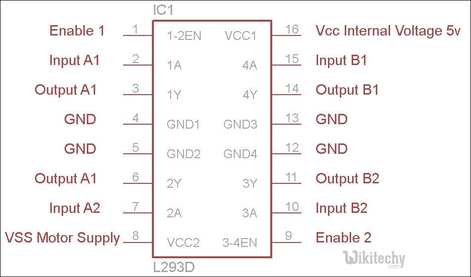
| Pin No. | Pin Characteristics |
|---|---|
| 1 - Enable 1-2 | when this is HIGH the left part of the IC will work and when it is low the left part won’t work. |
| 2 - INPUT 1 | when this pin is HIGH the current will flow though output 1 |
| 3 - OUTPUT 1 | this pin should be connected to one of the terminal of motor |
| 4,5 - GND | ground pins |
| 6 - OUTPUT 2 | OUTPUT 2, this pin should be connected to one of the terminal of motor |
| 7 - INPUT 2 | when this pin is HIGH the current will flow though output 2 |
| 8 - VCC2 | this is the voltage which will be supplied to the motor. |
| 16 - VCC1 | this is the power source to the IC. So, this pin should be supplied with 5 V |
| 15 - INPUT 4 | when this pin is HIGH the current will flow though output 4 |
| 14 - OUTPUT 4 | this pin should be connected to one of the terminal of motor |
| 13,12 - GND | ground pins |
| 11 - OUTPUT 3 | this pin should be connected to one of the terminal of motor |
| 10 - INPUT 3 | when this pin is HIGH the current will flow though output 3 |
| 9 - Enable 3-4 | when this is HIGH the right part of the IC will work and when it is low the right part won’t work. |