555 Timer LED Flasher - Block Diagram of IC 555 Timer
Block Diagram
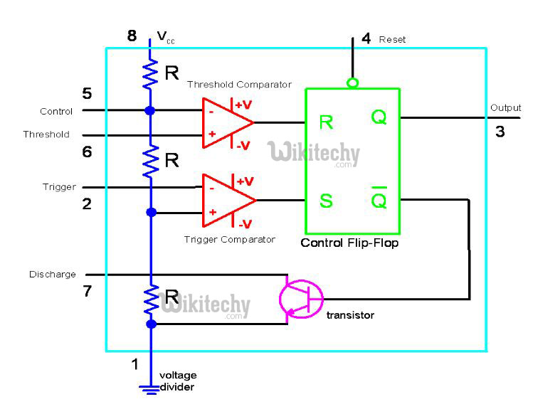
Block Diagram of IC 555
Inside the 555 Timer
- The voltage divider (blue) has three equal 5K resistors. It divides the input voltage (Vcc) into three equal parts.
- The two comparators (red) are op-amps that compare the voltages at their inputs and saturate depending upon which is greater.
- Threshold Comparator
- Trigger Comparator
- The Threshold Comparator saturates when the voltage at the Threshold pin (pin 6) is greater than (2/3)Vcc.
- The Trigger Comparator saturates when the voltage at the Trigger pin (pin 2) is less than (1/3)Vcc
- The flip-flop (green) is a bi-stable device. It generates two values, a “high” value equal to Vcc and a “low” value equal to 0V.
- When the Threshold comparator saturates, the flip flop is Reset (R) and it outputs a low signal at pin 3.
- When the Trigger comparator saturates, the flip flop is Set (S) and it outputs a high signal at pin 3.
- The transistor (purple) is being used as a switch, it connects pin 7 (discharge) to ground when it is closed.
- When Q is low, Qbar is high. This closes the transistor switch and attaches pin 7 to ground.
- When Q is high, Qbar is low. This open the switch and pin 7 is no longer grounded