555 Timer LED Flasher - Project Design - Description
555 Timer IC Pin Description
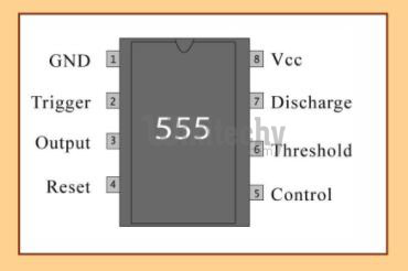
Pin Description
Ground Pin
- Ground pin is connected to the Ground.
Trigger pin
- The Trigger pin is connected to the capacitor.
- The capacitor is used for Charging and Discharging.
- Here using a 10 Micro Farad capacitor.
Output Pin
- The output pin is used to display the output that is the LED will blink when it is connected to the battery.
Reset pin
- The fourth pin is the reset pin , In this pin it connected to the battery supply.
- For consistent supply, we are using ARDUINO BOARD. Its not mandatory for using this arduino board we can use a battery itself.
- The arduino board is used to generate a 5V supply .
Control Voltage pin
- The pin five is not for usage, its just for controlling the voltage.
Threshold pin
- The pin 6 is threshold pin is connected to pin 7 with a resistor.
- In this pin we are using 10k ohm Resistor for doing some calculation.
Discharge pin & Vcc pin
- The pin 7 (discharge pin) and pin 8 (Vcc pin) is connected to another variable resistor of 5k ohm.